I have a 2 button latching footswitch that I want to use with the PS 100. I want to control the Channel Selector with the footswitch, but not the FX Loop Deactivate feature. I need the FX loop to be active at all times.
I also have a Champion Pure A/B+ switch that lets we switch between inputs on my Ampeg V-2 amp. The Champion Pure A/B+ switch has a remote input jack that can be controlled by a latching footswitch.
As I understand it the FX Loop is controlled by the RING/SLEEVE combination on the TRS jack.
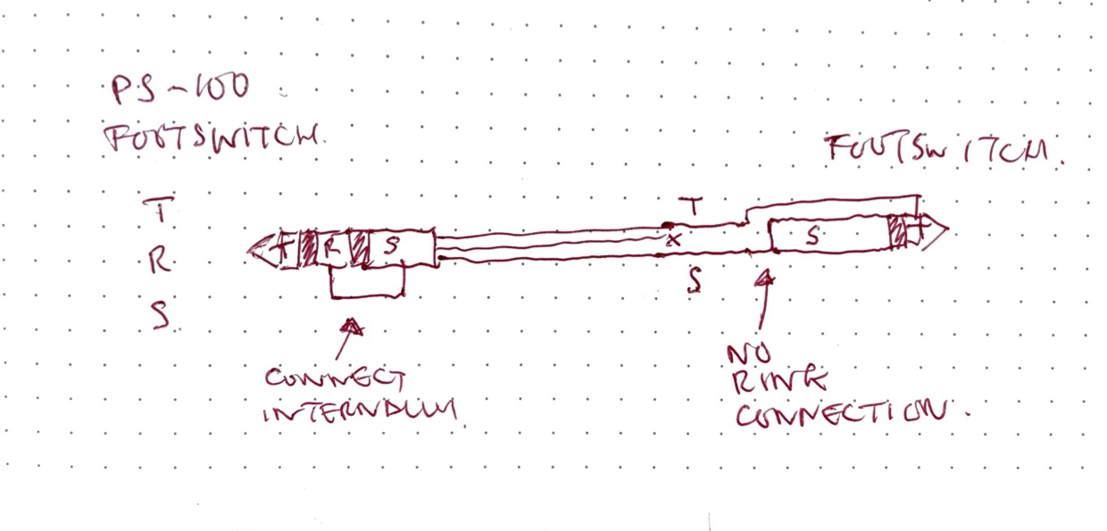
Now imagine connecting a TRS jack to the Footswitch input on the PS-100 that is wired up the following way:
TIP is as normal
RING is not connected
SLEEVE is as normal
The cable that was supposed to be connected to the RING is feed to a breakout cable together with the Sleeve, and in turn connected to the remote input jack on the Champion Pure A/B+ switch.
So the question is … using this cable configuration:
Will one switch control the PS-100 and the other the AB switch ?
If it works, what state will the FX Loop be set to ?
The alternative is to split the TRS cable into two TS cables.
What will the PS-100 do with regards to FX Loop status when a TS cable is inserted into the Footswitch input?
Yes, this will successfully break out the FX switching the second box
(Champion). When the switch is open FX loop will be off and when the switch is closed, the FX loop will be on.
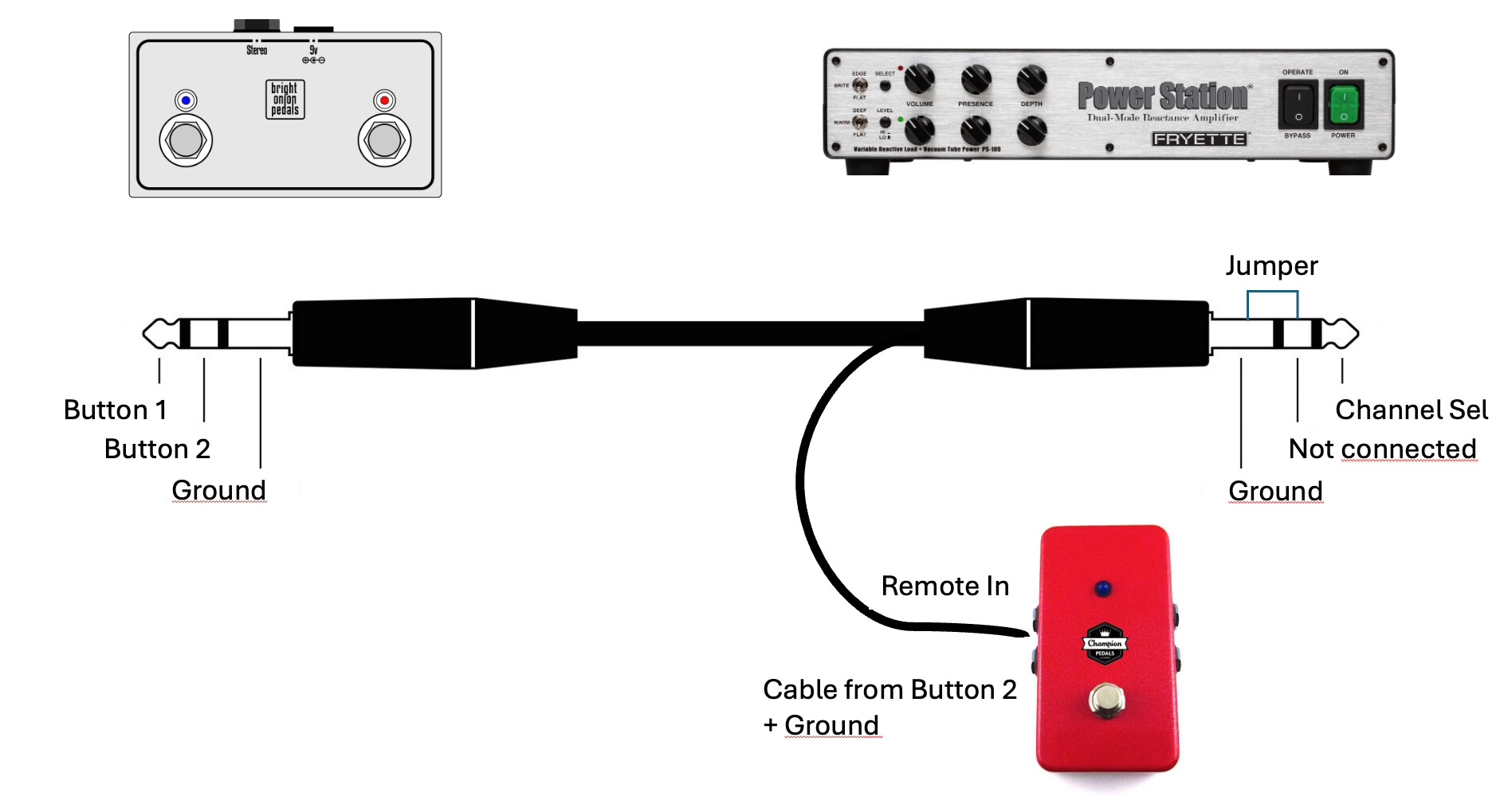
You would need the ring circuit to be closed (not open). To do this you could just jumper the ring pin to the sleeve pin on the socket in the footswitch. However, if it’s a single-button switch, you probably can’t do that because it will only be a tip-sleeve type. So maybe you could prepare a special TRS cable: TRS socket to TS socket. On the PS-100 side you solder together the ring to the sleeve and then on the other side just ignore the ring connection and solder the tip and normal to mono jack.
The jumper between ground and ring on the right-hand-side jack will tell the PS-100 to always have the FX loop enabled. This can’t be overridden by any switch further down the line.
I thought you wanted to use PS-100 with a single-button footswitch and always keep the FX loop on. Do you want to have FX loop switchable but in a dedicated foot switch?
Sorry if my explanation was unclear. Was I am after is shown in the drawing above. A two button footswitch, controlling only the Channel select for the PS-100 (button 1) and on/off on a A/B switch (button 2). The reason I need the FX loop on the PS-100 to be always on is that my GPDI/IR is connected there
again .. I am so sorry if I confused you. Not my intention at all
The great stuff is that we ended up with a solution I can use.