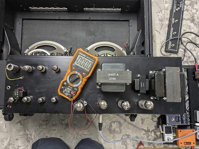
I recently aquired an old VHT C-100-CR combo, serial#: F950112 (reverb and GEQ)
Is therer still a manual around for this amp? This has 8(!) preamp tubes and 4 EL34 for the power section.
Hi Miro,
Welcome to the forum!
I’ll see if I can find anything here in the shop, but I’m not sure there will be anything. Most of our older documentation was lost in a server fire a few years back. So far the only things I can find are for the CLX line of amplifiers (EQ, no reverb), the Pittbull 45, and the SIG:X. I will let you know if we can locate any of the other models.
Thank You,
Terry
Thanks Terry! I think I can find most of the controls in the CLX manual tubes are shown on the backside of the amp itself.. Do you know the intended bias current for the EL34 power tubes? I measured about 40mA idle current.
Also when I pulled the amp from the chassis some more questions emerged. Do you still know with preamp tube does what?
The shielded tube must be V1, second in the lower row is a 12AT7 which sould be reverb. I guess the two closed right (12AX7 and 12AU7) are the PI, power tubes are clear. Still 4 12AX7 left that must do something…
Then there is a 6,3mm plug (left side between the shielded tube and the lower one. Any idea what this does?
Lastely I was suprised that the power connector shows to use 117V
We have 230V around here, maybe there was a sticker there that is gone, I’m pretty sure it would not still be working if it was made for half the voltage…
Hi Miro,
This is what we currently have on file for that amp. It describes the tube functions.
Serial # F950112 was built as a 117V unit. It may have been modified independently for 230V operation. A photo of the inside on the power transformer end of the chassis would be helpful.
CLASSIC COMBO REVERB.pdf (5.3 KB)
The bottom mounted phone jack is the reverb on/off switch.
Bias is typically 35-38mA.
Thanks,
Dave
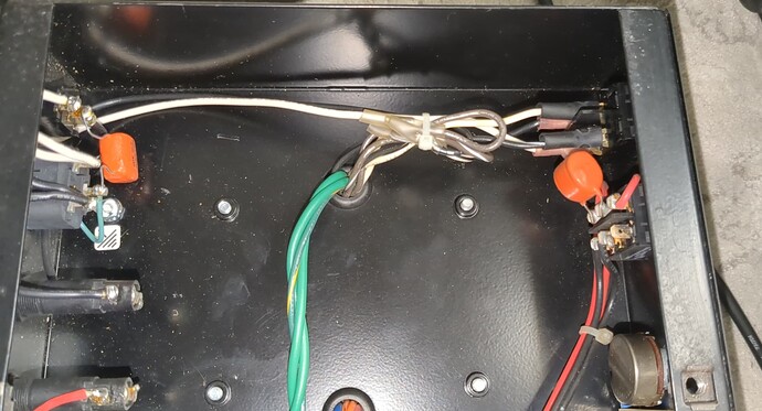
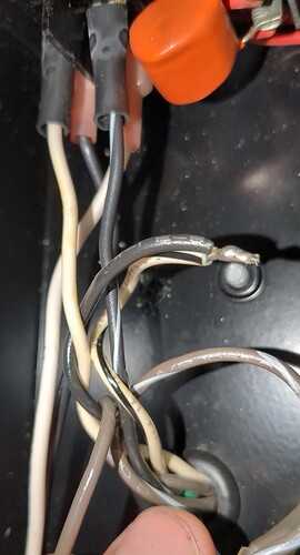
Thank you, that’s exactly the info I needed! Here is a picture of the area you requested:
Can the transformer handle multiple input voltages dependant on the used input cable colour code?
Yes.
That rewiring job is not factory, but I assume it’s working so probably OK.
Dave
Yes, it’s working, No idea, if the power transformer has 220 and 230V inputs, but even if it was wired for 220V it should be within tolerances I guess.
They bridged white/black to black, brown and brown /white are not connected. White and black / white are connected to the power switch. As I don’t have any schematics I can’t tell what this actually does, also I have no idea how it was wired originally.
As you say, it’s working and someone changed it, so chances are good they did it right
Yes, that looks OK!
Dave
Hey DavidPhelge—in the first photo in the thread, the bottom of the chassis, V1 has a shield, and the shield has a soldered wire running to a screw in the chassis. I’ve never seen that, and I have two of these things (one of them a 1995 like this). Any idea why that was done? Is for grounding purposes? Or is it simply to keep the shield “tied” to the chassis (lest it be lost?)
That’s not factory, but is of no consequence one way or the other.
Dave
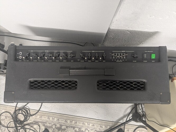
It seems this unit was modified quite a bit (Power transformer, ground on tube shield). Someone also put handles into the sides of the chassis and wheels on the bottom. I am not even sure if the chassis configuration is original, I have seen no pictures with a top mounted configuration of this amp before (and I do not think it is a particularly good idea):
Also it came with a V30 and a G12-M 25 installed, I changed it to two Vintage 30s as the previous confirmation had a max of 50W.
30 years of individual ideas
The cab with the handles on the sides and casters is original.
Stock speakers were Celestion Classic 80.
Probably 10 of those were ever built.
Dave


