Block diagram request (Cyclops and PS-2A)

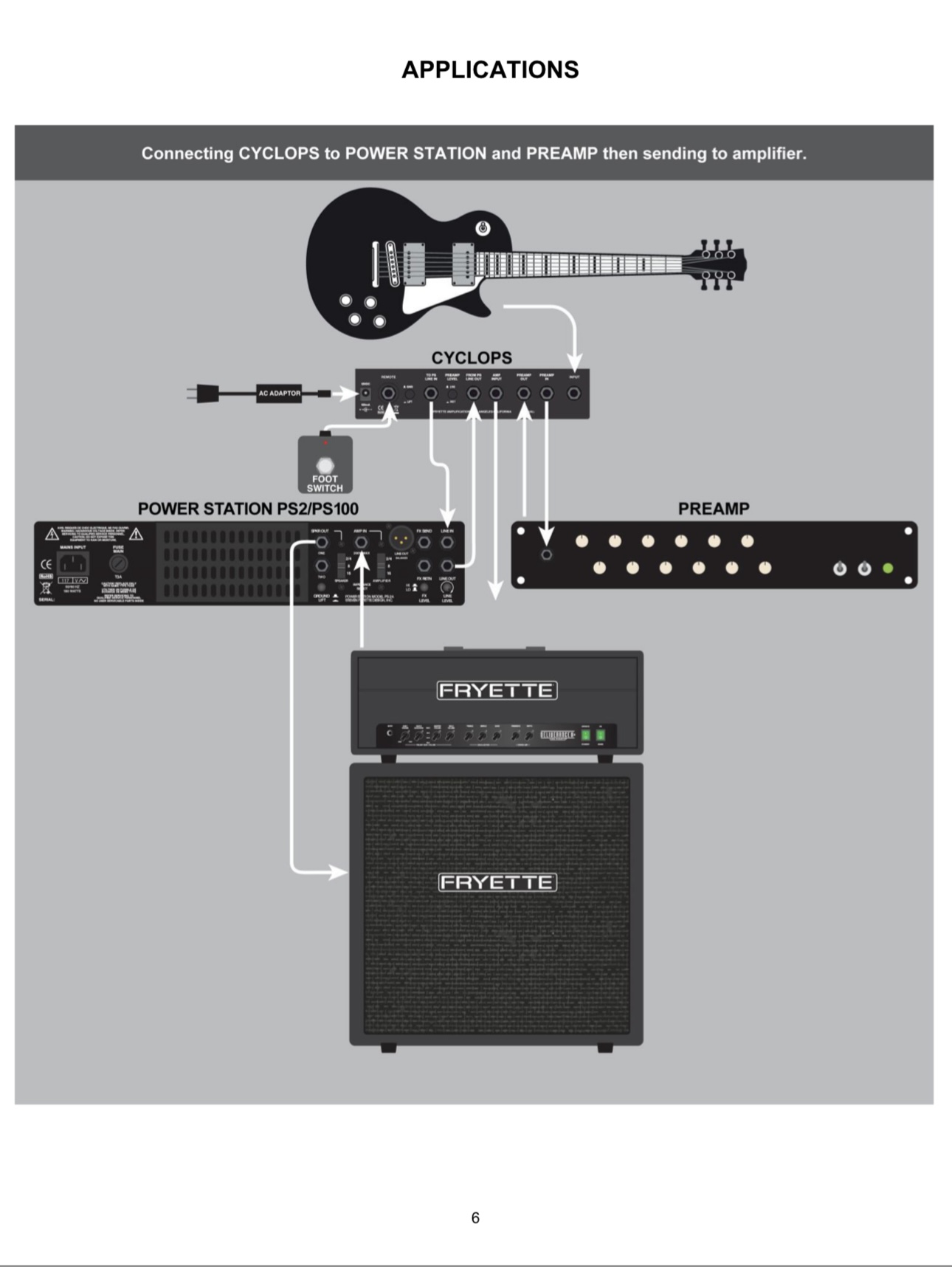
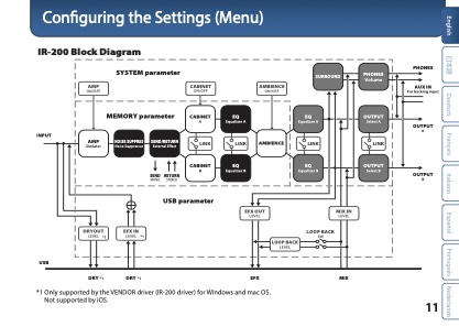
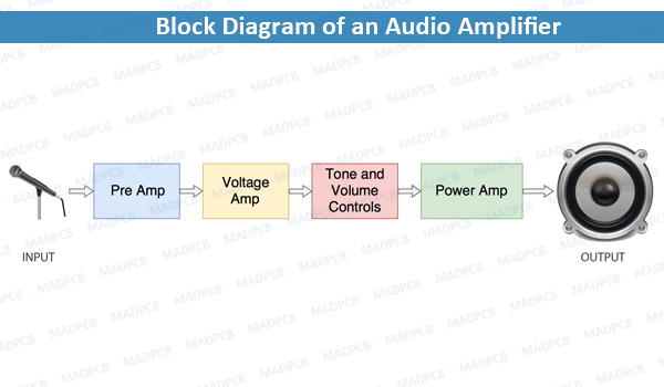
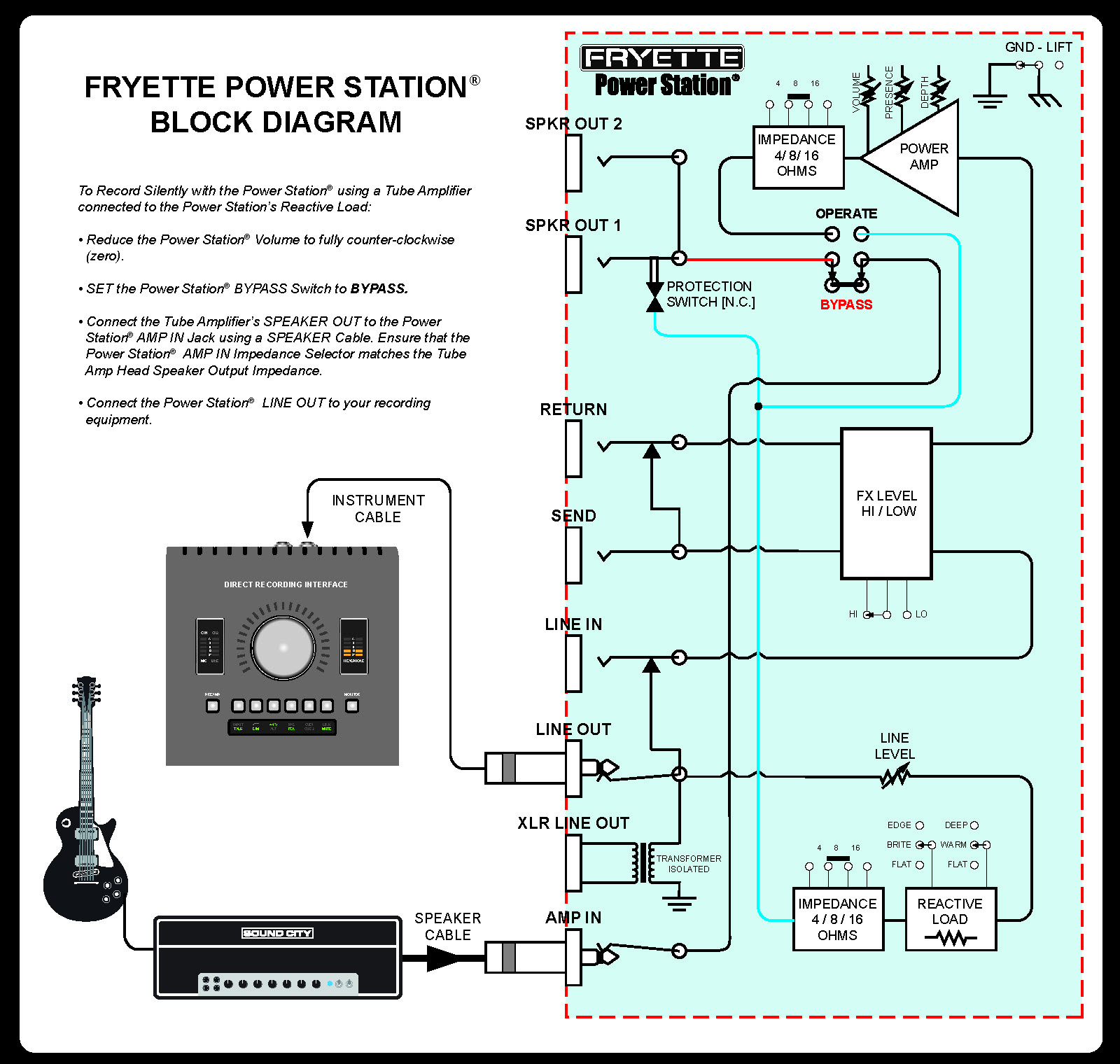
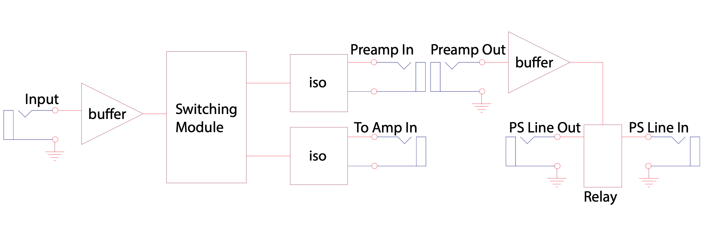
Please provide functional block diagrams of the Cyclops and PS-2A so I can tell if these products will work for my application.

I have watched all the videos, poured over the manuals and read the forum topics and I still don’t have a complete picture of how these products operate, or how I could properly integrate the PS-2A and Cyclops into my rig. I’m an electronics engineer so I know the issue isn’t me.

If I may respectfully offer a bit of practical advice: You really should include functional block diagrams in the manuals for the Cyclops and the Power Station products (both models). Trying to explain how things are connected inside these units using only text or talking about it is very limiting, inefficient, and really poses a potential danger to the equipment your customers already own because those methods do not adequately explain the functionality of your products, and misunderstandings could lead to equipment damage.

Yes, this stuff is fairly simple IF you’re the designer and you know what connections you made inside the black box you designed. But that information is not obvious to anyone else. “Connect this to that” labels and diagrams, and phrases like, “the line out sits between the load transformer and the power amp” impart only vague insight insight into the functionality of these units. You really owe existing and potential customers block diagrams detailing the internal signal paths and functionality of every knob, switch and jack on the front and rear panels of these devices. This is the norm for products like this.

I have a complex rig that I think could benefit from the use of your products, but I won’t be using them exactly the way you diagrammed things in the product manuals. For one thing, my rig is stereo and I I’m thinking of using two of your PS-2A units. And your Cyclops may or may not be an appropriate solution for my use case – I will not be able to determine this until I see the block diagrams. I won’t get into specifics of my own rig here because that isn’t the point of my post. I couldn’t be that unique of a person - if I have this need, I’m sure others do as well, though their rigs will undoubtedly be different than mine.

Your products are, in short, beautiful, and I’m looking forward to buying and using them. Please provide those block diagrams!

Thanks in advance!

Hi Zero,

Page six of the Cyclops manual has a great diagram of both units in operation together. If you are looking for more, this forum also has great diagrams for some extremely complex rigs. Even so far as adding in other companies gear with wiring diagrams. I’m not really sure how you got the notion there weren’t any. I’m sorry if you’re having trouble finding exactly what you want though. There are some great rig builders out there that do this kind of thing for a living. Usually they are available for information as well, they tend to charge for that information though because it’s not as straightforward as circuit design in most cases.

Also, most block diagrams don’t do anything in detail. The Cyclops is an extremely simple device that switches between two signal paths. The PS-2A (which there is a block diagram for) is a very simple design as well. Just using the block diagram for the PS-2A and PS-100 should let you know exactly what you’re looking for.

If you want to let us know what’s in the rig, I’d gladly try to help you out.

Hope the diagram works!

Thank You,

Terry

Hi Terry,

Thanks for the kind reply. I can see that you’re trying to help me out. But I don’t understand your reluctance to share some simple block diagrams with me (us, really, since this is a forum for all of your customers).

Judging from your answer, you seem to be confusing the term “block diagram” with wiring diagrams or application examples. I’m not asking for wiring diagrams or application examples. I’m asking for block diagrams. Those are the diagrams that describe the functionality of a product and how it relates to the controls and I/Os on the product. In other words, they tell us what is going on inside the product — not in a lot of detail, but just enough to know what the product is doing so we can use the product properly. To be clear, I’m not talking about schematics — I understand that those are proprietary information.

Two examples of block diagrams are attached — an excerpt from the manual of a music related audio product and a simple one off the Internet. The complexity of your products falls somewhere between these two examples.

I looked in the PS-2A manual again and it only contains application examples (wiring diagrams). And those wiring diagrams don’t show the use of every I/O. So they don’t serve the same purpose. Seeing a block diagram of each product will allow me to insure that I understand how the audio is routed, that I’m using the products properly and nothing is connected incorrectly, insuring the safety of my gear.

Without the block diagrams I cannot be confident that I understand the signal path and what is being done to that path at every stage, and therefore, not only would I lose control over my audio signal and how I want it routed, I will not be confident I can connect things properly and safely. It’s extremely easy to damage audio equipment by tying outputs together or doing something else equally bad. The list of ways to damage equipment is long so I won’t go on about it — I imagine you get my point. And even if I knew nothing would get damaged, I naturally want to know that I’m applying any gain or attenuation (like the line/instrument switch on the Cyclops) at a point in the audio path that makes sense for my rig. That’s just one example of why I (or anyone else) should know the functionality of your products and how that functionality relates to the I/Os and controls on your products. That information is most efficiently and accurately conveyed using block diagrams.

To further illustrate the need for those block diagrams, I took my best guess as to what the signal path was and found that it could not be determined, given the ambiguous labeling of the I/Os. You can’t even tell if a jack is an input or an output from the labels. My attempt at determining this is attached. Note the question mark.

In the spirit of cooperation I’m sharing a simplified wiring diagram of a new rig I am developing. (I have made similar rigs in the past with great success.) Please feel free to advise me as to how much of the switching could be done using the Cyclops, and please point out where those isolation transformers in the Cyclops could help. I’d also like to know where the line/instrument switch lies in the signal path. Of course, if I could see the block diagrams I would not need any of this help. Nor would anyone else. The simplest and easiest way to help, by far, would be to provide the block diagrams.

I hope you understand the issue better now and are willing to share some simple block diagrams. I don’t think this is a lot to ask, and I don’t feel that this is asking anything unusual or above the norm.

Thanks in advance!

Best regards,

ZeroImpedance


Signal path is unclear.pdf (456.1 KB)
Stereo Marshall - Tone King idea.pdf (426.5 KB)

Hey ZeroZ

Do you mean this? We only have one of these for the Power Station because it’s pretty unique and has a lot of functionality.

1 Like

This is the best I could do in short notice. It should explain how the system works. Like I said, we don’t mind helping. As for the instrument/line switch, it acts on the buffer section to bring the level to where you need it. Looking at your rig though, I have to ask, how were you wanting to use the Cyclops? Are you adding a preamp or preamp pedal to your rig?

Thank You,

Terry